Virtual doorbell

We had some cameras installed at our house last year, partly for security, but mainly so we could know who is at the door before answering it in our PJs. Unfortunately, the software that comes with the camera DVR is pretty clunky, so it takes way too long to bring up the feed when the doorbell rings and I often don’t bother.

Luckily, the DVR exposes RTSP streams that you can capture and playback with your favorite mpeg player. And I just learned how to build a pretty good image classifier that needed a practical application.

A ridiculously good-looking person is at the door

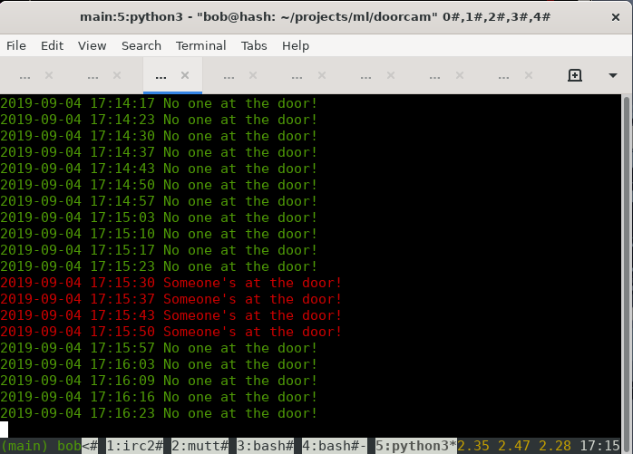
Thus, I built an app to tell whether someone is at the door, before they ring the bell. I labeled some 4000 historical images as person or non-person, trained a CNN, and made a quick python app to run inference on the live feed. When a person is in range of the door camera, it aims the lasers tells you so.

Doorbell MVP

Not bad for having two whole weeks of deep learning under my belt. The interface could stand to be much better, of course. A little web page that sends a browser notification and link to the image or live feed would be the obvious next step. Perhaps the lasers are after that.

I know this is something that comes out of the box with commercial offerings such as Ring, but at least my images aren’t being streamed to the local police.

In which I trained a neural net

The entire sum of my machine learning experience thus far is a couple of courses in grad school, in which I wrote a terrible handwriting recognizer and various half-baked natural language parsers. As luck would have it, I was just a couple of years too early for the Deep Learning revolution — at the time support vector machines were all the rage — so I’ve been watching the advancements of the last few years with equal measures idle interest and bewilderment. Thus, when I recently stumbled across the fast.ai MOOC, I couldn’t resist following along.

I have to say I really enjoy the approach of “use the tools first, then learn the theory.” In the two days since I started the course, I already built a couple of classifiers and got very good results, much more easily than with my handwriting recognizer of yore.

My first model was trained on 450 baby pictures of my children and achieved 98% accuracy. Surprisingly, the mistakes did not confirm our priors, that Alex and Sam look most similar as babies — instead it tended to confuse them both with Ian. The CNN predicts that I am 80% Alex. Can’t argue with that math.

The second classifier was trained on Pokemon, Transformers, and Jaegers (giant robots from Pacific Rim). This gets about 90% accuracy; not surprisingly, it has a hard time telling apart the robot classes, but has no trouble picking out the Pokemons.

I’m still looking for a practical application, but all in all, it’s a fun use for a GPU.

More filler

I noticed some HTML5 crossword construction apps have sprung up over the last year, so I no longer have first mover status on that. Also their UIs are generally better and I dislike UI work, so it seemed reasonable to join forces. Thus, I sent some PRs around.

It was surprising to me that the general SAT solver used by Phil, written in C compiled to asmjs was so much slower than a pure Javascript purpose-built crossword solver (mine). I assumed the SAT solver might make certain search optimizations that could overcome the minor optimizations related to mine being only a crossword solver. So, yay, my code is not that bad?

In these apps the filler runs as a web worker so even when slow it isn’t too noticable (except for hogging a core).

Anyway you can try out my filler today with Kevin (filler code is here, which is exactly the code in my own app except with some janky whitespace because I stripped out all flow annotations).

Router redux

I had just a little bit of downtime over the last few weeks while Angeline and I reacquainted ourselves with how to take care of an infant. It’s like riding a bicycle: there are tons of things you forgot since last time.

One of the long-on-my-todo-list items finally got completed: I upgraded all of my wifi routers. I have 5: an old dual band 11n router and four TP-Link 11ac units, all of which were running some oldish build of OpenWRT.

I decided the 11n router’s time has come for the trash-heap, so I put the latest stable LEDE build on one of the TP-Links and swapped it out.

The other three are just access points without the router: they just have all the ports on the unit bridged together, connected to the router via a wired switch. I also have a mesh wifi interface up on each unit so that I could place the unit anywhere regardless of wired connectivity (though, in practice, I have wired drops everywhere so I don’t really use this.) For these, I build from source with just the required bits. I added a serial port to one of the units so I can test builds there before rolling out to the other two.

In all it was pretty painless since the LEDE build is more or less the same as OpenWRT. I did go through (LEDE) recovery once and found this fun issue:

root@(none):/tmp# sysupgrade -n lede-ar71xx-generic-archer-c7-v2-squashfs-sysupgrade.bin
Image metadata not found
killall: watchdog: no process killed
Commencing upgrade. All shell sessions will be closed now.
Failed to connect to ubus
root@(none):/tmp#

…because sysupgrade has different paths for failsafe vs not; and for some reason $FAILSAFE is not always set. Do this to work-around:

root@(none):/tmp# export FAILSAFE=1
root@(none):/tmp# sysupgrade -n lede-ar71xx-generic-archer-c7-v2-squashfs-sysupgrade.bin
Image metadata not found
killall: watchdog: no process killed
Commencing upgrade. All shell sessions will be closed now.
root@(none):/tmp# Connection to 192.168.1.1 closed by remote host.

React reaction

An embarrassing admission to make: I wrote something in javascript.[1]

Actually, I wrote it in React, because I still think of javascript as that awful language that works differently in every browser, and so, you know, to stay relevant, I decided to learn the framework that web developers everywhere have already cast into yesterday’s wastebin for the new shiny. This, pretty much.[2]

Anyway, I replaced the third-party crossword app on my website with my own NIH version and made it somewhat responsive [3] so that it works on my phone. Also there are two new-ish puzzles since the last time I posted, dated 2016-11-25 and 2016-12-30. Each of them has its own set of problems, but I think I am at least learning where I need to improve.

To this neophyte, my impression is that using React (and ES6) is much nicer than that terrible language that they compile down to. On the other hand, the pattern of moving state up the object hierarchy away from an object’s view feels backwards and not very OO-like. Perhaps if I also used Flux then I might get enlightened on this point, but that is for another day.

[1] Here’s a nickel, kid. Buy yourself a real language.
[2] The day that my relevance depends on knowing the latest JS framework is the day that I will take up a completely different career.
[3] Anything worth doing is worth doing somewhat.

Fake clicky

In the previous installment I had opined about the untapped power inside my new mechanical keyboard. I haven’t had much time to continue looking into the firmware, but I did find the original source of the firmware tools for a similar product. His blog post is well worth a read.

Thus far the new device is performing admirably, but it did come with an unforeseen problem.

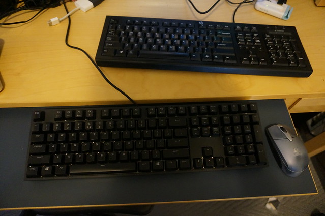
I always have a bunch of computers here at my desk, and so for some time I’ve had a physical KVM switch to share a single monitor and input devices among them. This switch has a special USB port on the back just for the keyboard, which it monitors for the double-scroll-lock macro command to switch the display. Unfortunately, said port will not power the new keyboard and also won’t work with a hub.

So, this happened:

Sad 2-keyboard desktop

One for switching, one for typing.

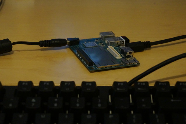
Inspired a bit by Johannes Berg’s (more interesting) uSynergy HID project, I thought I’d see if I could bang up a “keyboard” that just lets me put the minimal bits on the wire to make the KVM happy. I had a Dragonboard (Arm64 SBC) already sitting around, and it supports OTG out of the box. Linaro publishes nightly Debian snapshots for it so getting the device up and running with Linux userland is painless.

The only real work involved is to build a new kernel with the USB HID function drivers. Pretty standard fare except the 96boards wiki is somewhat confusing as to where to get all the pieces; here are my unedited notes:

Initrd: http://builds.96boards.org/snapshots/dragonboard410c/linaro/debian/latest/initrd.img-*
Toolchain: http://releases.linaro.org/14.11/components/toolchain/binaries/aarch64-linux-gnu/gcc-linaro-4.9-2014.11-x86_64_aarch64-linux-gnu.tar.xz
skales: git clone git://codeaurora.org/quic/kernel/skales
Linux repo: https://github.com/rsalveti/linux.git
Branch: qcomlt-4.4
defconfig: distro.config

export ARCH=arm64
export CROSS_COMPILE=~/ext/dragonboard/gcc-linaro-4.9-2014.11-x86_64_aarch64-linux-gnu/bin/aarch64-linux-gnu-
make defconfig distro.config
make -j8 Image dtbs
make modules modules_install INSTALL_MOD_PATH=../dragonboard

../skales/dtbTool -o dt.img -s 2048 arch/arm64/boot/dts/qcom/
../skales/mkbootimg --kernel arch/arm64/boot/Image \
  --ramdisk initrd.img \
  --output boot-db410c.img \
  --dt dt.img \
  --pagesize 2048 \
  --base 0x80000000 \
  --cmdline "root=/dev/disk/by-partlabel/rootfs rw rootwait console=ttyMSM0,115200n8"

* rsync modules to rootfs
* fastboot to boot or flash the kernel

With the kernel built and booted, I copied this setup mostly verbatim to get a functioning HID device.

And then the only “code” needed is a little shell script to send my switching sequence:

#!/bin/bash
function send_keycode {
	echo "keycode: $1"
	local keycode=$1
	echo -ne "\x00\x00"$keycode"\x00\x00\x00\x00\x00" > /dev/hidg0
	echo -ne "\x00\x00\x00\x00\x00\x00\x00\x00" > /dev/hidg0
	sleep .1
}

function num_keycode {
	local num=$1
	local ord=$(printf "%d" \'$1)
	let kval=$(($ord - 49 + 30))
	char=\\x$(printf "%x" $kval)
	echo $char
}

cd $(basename $(dirname $0))
visible=$(cat .switch.cur || echo "1")
case $1 in
	--up) screen=$(( (visible + 1) % 4)) ;;
	--down) screen=$(( (visible + 4 - 1) % 4)) ;;
	[1234]) screen=$(( $1 - 1 ));;
	*) echo "Usage: $0 [--up|--down|[1-4]]"; exit 1 ;;
esac

echo Switching to screen $(( screen + 1 ))
echo $screen > .switch.cur

# send: 2 x scroll lock, [1-4], enter
send_keycode "\x47"
send_keycode "\x47"
send_keycode $(num_keycode $((screen + 1)) )
send_keycode "\x28"

The volume buttons on the Dragonboard still work when the device is in OTG mode, so I used xbindkeys to bind volume up to “switch.sh –up” and likewise for down.

Happy 2-keyboard desktop

Much better.

Yes, this is pretty ridiculously overpowered for what it is, and I’ll probably replace this with an MCU build when I get some time, but still it is fun to think about having a keyboard that runs X.

Clicky

I got a new keyboard this week with 80s-era clickiness: a Cooler Master QFR XTi.

This thing has LED-backlit keys, which is kind of fun but also a bit of a gimmick. More interesting to me is that driving everything is an ARM Cortex M3 MCU (Holtek HT32F165x) which is flashable over USB. That is more powerful than my first computer.

It would be nice to expand the features of this thing a bit, e.g. there’s an RTC on board the MCU, wouldn’t it be useful to have TOTP built directly into the keyboard? Or, perhaps it would be useful to audit the vendor firmware to make certain it is not recording your keystrokes. Of course, getting to the point of unraveling the vendor FW and flashing one’s own will entail a fair amount of work.

It seems there is support for SWD programming and pads for that on the motherboard, but given my clunkiness with a soldering iron that is kind of a last-resort thing to revisit once I brick my keyboard.

Anyway, I captured the firmware upload via USBPcap in Windows. Turns out it’s a fairly simple protocol. I saw the following two messages cross the wire:

MSG 1:

01 01 53 b6 38 2d 00 00 6b 2d 00 00 73 2d 00 00
00 00 00 00 00 00 00 00 00 00 00 00 00 00 00 00
00 00 00 00 73 2d 00 00 07 48 80 47 07 48 80 47
07 48 00 47 fe e7 fe e7 fe e7 fe e7 fe e7 fe e7

MSG 2:

01 01 84 0d 6c 2d 00 00 9f 2d 00 00 fe e7 fe e7
fe e7 fe e7 ad 7b 00 00 4d 71 00 00 81 2d 00 00
df f8 0c d0 00 f0 3e f8 00 48 00 47 e5 84 00 00
60 47 00 20 06 49 07 4a 08 68 50 43 43 f2 39 02

It is reasonable to assume that the “fe e7” chain repeats without a break across the two messages, which in turn tells us that the header for the message is twelve bytes:

    msg 1: 01 01 53 b6 38 2d 00 00 6b 2d 00 00
    msg 2: 01 01 84 0d 6c 2d 00 00 9f 2d 00 00

Bytes 4-8 and 8-12 look like addresses in little endian format. As it happens, if you subtract these two addresses and add one, you get the value 52, which is exactly how many post-header bytes are in the message. Also note that the “address 1” in message two is just one more than the “address 2” in message one. So we have something that looks like this:

    struct hdr {
        u8 cmd;                         /* ??? */
        u8 subcmd;                      /* ??? */
        __le16 something;               /* ??? -- crc? */
        __le32 start_dest_address;      /* first byte of xfer */
        __le32 end_dest_address;        /* last byte (inclusive) */
        u8 data[0];
    };

The device presumably copies the payload from “data” into the physical (flash) addresses specified in the header.

So I dumped the firmware from the pcap file. There’s nothing like an ELF header on it, but I guess that’s probably normal for bare-metal programs running on an MCU. Various bits do look like ARM thumb code.

Until now I didn’t really know squat about ARM MCUs, but a little bit of googling indicates that E7 FE is an infinite loop and the typical way you would write a handler for something like NMI that you just want to go into loop mode. So that explains the 0xfee7 sequence, and everything before looks like a lot of little-endian 32 bit addresses, which lines up with what would go in the Vector Table, an ARM concept which contains the values for program counter load address, stack pointer, IRQ handlers, and so on.

A bit more googling found some github projects with functional flashing utilities for similar products with similar or the same flashing protocol. There is yet hope, hopefully more to come.

On Drawing Squares

I’ve been looking at the sample drawing in speccy to try and speed it up. For a given frame, it renders about 10000 points as 9-pixel anti-aliased squares using Cairo, in Python. On my desktop (Debian stable, Nouveau driver) it gets a pokey 1 FPS.

My graphics knowledge is about 20 years old at this point, and while I did once know various arcane tricks on the hardware of the day, none of that is relevant now. So I know basically nothing about modern graphics. It is still not clear to me to what extent the 2D primitives use acceleration, and it doesn’t help much that, in as many years that I’ve been asleep on this topic, there seems to have been as many new APIs introduced and retired: today there are at least XRender, XAA, EXA, UXA, SNA, and Glamor — did I miss any?

Anyway, here are the results on my desktop from things that I’ve tried so far [1]:

test                    FPS
----                    -------
orig (aa)                0.904780
no_aa                    1.103061
no_cairo                 8.372354
no_cairo_aa              2.408143
batched                 19.873722
batched_aa              29.045358
batched_by_color         7.611148
batched_by_color_aa     14.856336

The tests are:

  • orig: the current code, where each rectangle is filled immediately in turn.
  • no_cairo: I skip Cairo completely and manually render to a GdkPixbuf internally, under the theory that draw function call overhead is the big killer
  • batched: using Cairo with one cr.fill() call for all of the rectangles. This means all are rendered with the same color, and as such could not actually be used. But it is interesting as a data point on batching vs. not.
  • batched_by_color: one cr.fill() call per distinct color
  • aa refers to having antialiasing enabled

Batching appears to make a huge difference, and binning and batching by color is the most performant usable setup. It’s not really difficult to batch by color since the colors are internally just an 8-bit intensity value, though in my quick test I am hashing the string representation of the float triples so it’s not as quick as it could be.

I don’t understand the performance increase on batching with AA applied. Perhaps this is an area where some sort of acceleration is disabled when AA is also disabled? This is a repeatable outcome on this hardware / driver.

Then I tested on my laptop and got these numbers (Debian Testing, Intel graphics):

test                    FPS
----                    -------
orig (aa)               28.554757
no_aa                   27.632071
no_cairo                 9.954314
no_cairo_aa              2.958732
batched                 43.917732
batched_aa              28.750845
batched_by_color        19.933492
batched_by_color_aa     19.803839

Here, just using Cairo is the best. My guess is batching by color is only worse because of the higher CPU cost of the hashing and the rather inefficient way I did it. Given the close performance of batched_aa and the original test though, batching done well probably isn’t going to make much difference.

Finally, I went back to the desktop and tried Nvidia binary drivers (oh, how I don’t miss those).

test                    FPS
----                    -------
orig                     6.586327
no_aa                   15.216683
no_cairo                 9.072748
no_cairo_aa              2.368938
batched                 39.192580
batched_aa              27.717076
batched_by_color        18.681605
batched_by_color_aa     16.450811

It seems Nouveau still has some tricks to learn. In this case AA is, as expected, slower than non-AA. Overall, batching still seems to give a decent speedup on this hardware, so I may look into actually doing that. Moral of the story: use the laptop.

As for speccy, I actually had a use for it recently: I needed to see whether a particular testmode on ath5k was functional. Although I can’t really measure anything precisely with the tool, I can at least see if the spectrum looks close enough. Below is a snapshot from my testing, showing that in this testmode, the device emits power on 2412 MHz with a much narrower bandwidth than normal.
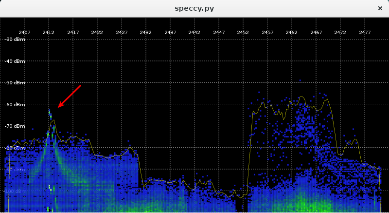
This matches, as far as I can tell, the spectrum shown on the NDA-encumbered datasheet.

[1] Approaches not tried yet: reducing the point count by partial redraws, using something like VBOs in GL, or rewriting parts in C. Feel free to let me know of others.

memory µ-optimizing

While looking at some kmalloc statistics for my little corner of wireless, I found a new tool for the toolbox: perf kmem. To test it out, I ran a simulated connected 25-node mesh in mac80211_hwsim.

Here’s what perf kmem stat --caller had to say:

---------------------------------------------------------------------
 Callsite            | Total_alloc/Per | Total_req/Per  | Hit   | ...
---------------------------------------------------------------------
 mesh_table_alloc+3e |      1600/32    |       400/8    |    50 |
 mesh_rmc_init+23    |    204800/8192  |    102600/4104 |    25 |
 mesh_path_new.const |    315904/512   |    241864/392  |   617 |
[...]

The number of mesh nodes shows up in the ‘Hit’ column in various ways: we can pretty easily see that mesh_table_alloc is called twice per mesh device, mesh_rmc_init is called once, and mesh_path_new is called at least once for every peer (617 ~= 25 * 24). We might scan the hit column to see if there are any cases in our code that perform unexpectedly high numbers of allocations, signifying a bug or poor design.

The first two columns are also interesting because they show potentially wasteful allocations. Taking mesh_table_alloc as an example:

(gdb) l *mesh_table_alloc+0x3e
0x749fe is in mesh_table_alloc (net/mac80211/mesh_pathtbl.c:66).
61		newtbl = kmalloc(sizeof(struct mesh_table), GFP_ATOMIC);
62		if (!newtbl)
63			return NULL;
64
65		newtbl->known_gates = kzalloc(sizeof(struct hlist_head), GFP_ATOMIC);
66		if (!newtbl->known_gates) {
67			kfree(newtbl);
68			return NULL;
69		}
70		INIT_HLIST_HEAD(newtbl->known_gates);

We are allocating the size of an hlist_head, which is one pointer. This is kind of unusual: typically the list pointer is embedded directly into the structure that holds it (here, struct mesh_table). The reason this was originally done is that the table pointer itself could be switched out using RCU, and a level of indirection for the gates list ensured that the same head pointer is seen by iterators with both the old and new table. With my rhashtable rework, this indirection is no longer necessary.

To track allocations with 8-byte granularity would impose an unacceptable level of overhead, so these 8-byte allocations all get rounded up to 32 bytes (first column). Because we allocated 50 of them (25 devices, two tables each), in all we asked for 400 bytes, and actually got 1600, a waste of 1200 bytes. Forty-eight wasted bytes per device is generally nothing worth worrying about, considering we usually only have one or two devices — but as this kmalloc is no longer needed, we can just drop it and also shed a bit of error-handling code.

In the case of mesh_rmc_init, we see an opportunity for tuning. The requested allocation is the unfortunate size of 4104 bytes, just a bit larger than the page size, 4096. Allocations of a page (so-called order-0 allocations) are much easier to fulfill than the order-1 allocations that actually happen here. There are a few options here: we could remove or move the u32 in this struct that pushes it over the page size, or reduce the number of buckets in the hashtable, or switch the internal lists to hlists in order to get this to fit into 4k, and thus free up a page per device. The latter is the simplest approach, and the one I chose.

I have patches for these and a few other minor things in my local tree and will send them out soon.

sae.py

For a while now, I’ve wanted an easy way to decrypt a mesh packet capture when I know the SAE passphrase. This would be quite handy for debugging.

I reasoned that, if I knew the shared secret, and had captured the over-the-air exchange, it should be possible to make such a tool, right? We know everything each station knows in that case, don’t we?

So I spent a bit of time last week reimplementing SAE in python to come to grips with its various steps. And I found my reasoning was flawed.

Similarly to Diffie-Hellman, SAE exchanges values that include the composition of a random value (we’ll call them r1 and r2) with some public part P, in such a way that it is hard to extract r1 even if you know P (e.g. r1*P and r2*P with ECC, although this is not exactly how SAE is specified). These values can be used by each peer to arrive at a shared secret provided they know the original random number (e.g., something like r1 * r2 * P). The crucial point is that r1 and r2 cannot be determined from the exchange alone. They exist only in memory on each peer during the exchange.

So if the secrecy doesn’t actually depend on the password, what is it there for? The answer is authentication: SAE is a password authenticated key exchange (PAKE). The password ensures that the party we are talking to is who we think it is, or at least someone who also knows the password. In the case of SAE, P is derived from the password.

As for the original goal, what we can do instead is use the CCMP keys from a wpa_supplicant log and decrypt frames with those. That is not nearly as convenient, though.

And thus my postings for 2015 are at an end; happy new year, all!