Amped

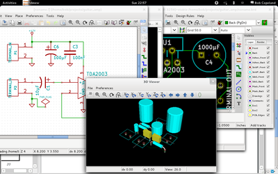
Some progress has been made on my guitar chip amp. Readers may remember that at the time of my last post, I had tinkered with KiCad and created the basic layout for my PCB. Since then, I finalized the design and had it fabbed through the great OSH Park batch prototyping service. This is a great deal: it wound up being about $10 a board (you get three at $5/sq. in) and the boards are of excellent quality. It took about 3 weeks from time of design submission for the finished boards to arrive in Canada from the States.


Practice amp PCB - topPractice amp PCB - bottom

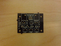
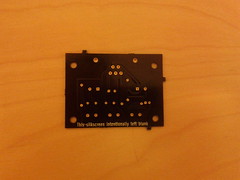
Above are the top and bottom of one the unpopulated boards. The solder mask is the OSH Park signature purple, and the through-holes are gold-plated. The bottom side silkscreen says “This silkscreen intentionally left blank” — a last minute addition because the service’s design checks fail if any layers are missing. I should get more creative with that next time.


Speaker box practice amp

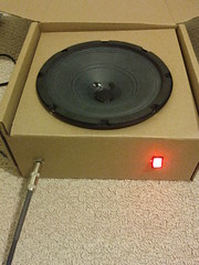
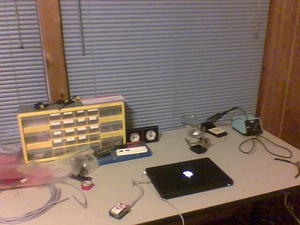
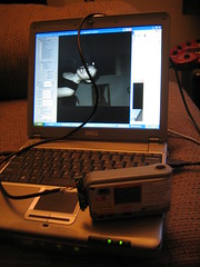
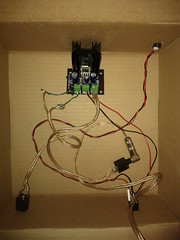
Although I do plan to someday build a wooden speaker cabinet to house everything, for now I just shoved all the electronics in the box that the speaker came in, as it happens to be the right size. Plug the instrument cable in the front, flip on the illuminated switch, and one is ready to rock.

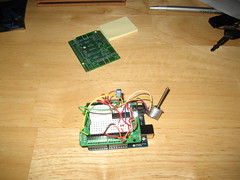
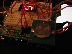
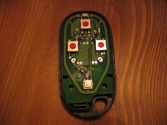
I had all the parts waiting for the boards, so when they arrived I quickly populated one and hooked it up, plugged in my Les Paul and strummed an E chord. The resulting sound was something short of musical: loud, ringing, distorted noises were heard instead of the clear tones of my prototype. I feared that my board design was flawed, and without a scope handy, it would be tough to track down. But on the plus side, I knew that I was about to learn something.

I spent an hour or so following all of the traces on the board and comparing them to the schematic, making sure the caps were all connected the right way around and so forth. I also compared the finished board to my protoboard, which happened to work fine. Everything was the same, except where I had used two 1 ohm resistors in series to invent a 2 ohm resistor (the datasheet called for a 2.2 which I didn’t have at prototyping time).

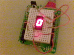
Then I looked at said resistors a little more closely. On the outside edge, I could just make out a faint yellow band where I previously thought there was none. And that brown band was just the tiniest bit in the purple spectrum. Oops! My 1 ohm resistors were actually 47 ohms, making the gain of my prototype a measly three instead of the 101 I thought it was. It turns out that a gain of 101 is way too high without a volume knob. Also, one of the 47-ohm resistors was in a stabilizing RC circuit, likely causing the ringing oscillations I had heard in my PCB version.


Practice amp populated

I fixed the RC circuit when building board number two, but stuck with the 2.2 ohm resistor and accompanying large gain. I might use this version if I decide to put a volume knob in front of the amplifier, but I do find it’s a little too noisy overall for my tastes. I thus went back to board number one, desoldered the 47 ohm and 2.2 ohm resistors and replaced them with 1 ohm and 22 ohm resistors respectively, lowering the gain of that board to a modest eleven.


Practice amp prototypePractice amp PCB guts

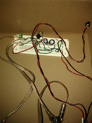
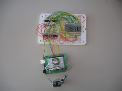
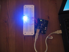
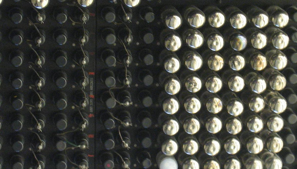
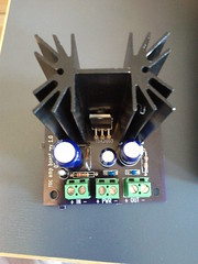
Pictured above are the before and after of prototype and PCB versions. There are certainly a few things I would change if I ever make another revision of the PCB. For one, the annular rings on the heat sink and connector footprints were too small, so soldering them was difficult with so little of the pad exposed. I might also do away with or reduce the size of the ground plane; even with the thermal reliefs, soldering and desoldering the ground connections was no easy task. But on the whole, making the PCB was an interesting experience and I look forward to having another excuse to do so again.

I’ll put the design files up on github one of these days.

KiCad Level 0 Achieved

When we moved to Canada, I sold any guitar gear that wouldn’t fit in a backpack. This has left me without the ability to plug in my electric guitar for the last ten months, a situation that must be rectified (ha, ha). I just need a small practice amp, and those can be found on an IC these days. One needs only to add a little soldering, attach a speaker, repeat as necessary for whatever mistakes one makes, and ta-da: a small custom amp that one could have bought mass-produced from China for 1/50th of the price of building one’s own. But of course there is value in the making, or so we tell ourselves.

Anyway, I’ve built my circuit (more or less the same one as on the op-amp’s datasheet) on a breadboard and it sounds fine except for the complete lack of shielding. Since it’s now possible to get one-off PCBs without spending a fortune, and using a real board is more fun than protoboards, let’s do that!

Back in the dark ages, I used to work on a PCB software that sold for $30k/license (I thought that was ridiculous then too). While I seem to have stuffed some arcane knowledge about keepouts and autorouters somewhere in the back of my brain, most of the PCB black magic did not rub off on me. After a 15-year hiatus from that domain, I can firmly label myself “PCB novice.”

Eagle Light (free as in beer) is the choice of many a hobbyist. I have poked at Eagle before, but never liked it enough to do anything substantive. These days, getting it to run at all means finding library versions that aren’t used in any current Linux distribution, building them, doing some LD_LIBRARY hacks, setting up a 32-bit runtime, and so on. Yes, I also did that this weekend. Eagle has a nice big standard library, but I feel learning it at all is a bit of a dead end when there are usable, truly free alternatives. And KiCad looks like it just may fit the bill. I apt-get installed it and was off to the races.

Overall, KiCad is a nice piece of FOSS software that can easily do whatever one would do in Eagle. Unfortunately, it still reminds me of what I hate about PCB software in general. I find designing a PCB to already be extremely fiddly and unfun; as a non-expert, I just want to build a schematic and then place and route things with sensible defaults. Instead, what I wound up doing was learning to use the symbol editor, and the module editor, gathering various facts about drill and pad sizes, and picking up KiCad’s various quirks such as how you have to constantly reload newly created libraries, and how the UI frequently makes no sense. Of course, UIs never make any sense in EDA tools, so you sometimes just have to go with it. Doing librarian work is ultra-boring, especially for tiny boards like this.

Still, in the course of a few hours, I built the basic schematic (including adding three new symbols), passed ERCs, created three missing footprints, and did an initial routing of the board. Not too bad.

In the last decade component libraries have grown 3-D models, which is kind of neat. On the one hand, it’s not terribly useful since the canned components are unlikely to closely match reality, and editing 3-D models of components is even less interesting to me than editing their footprint. But, it does make for decent screenshots like the one above.

Stepper motor


Stepper motor
Originally uploaded by bluesterror

For a future project, I pulled a stepper motor from an old 3.5″ disk drive and hooked it up to my Arduino. Turns out it’s quite easy to control these things: just periodically write bit patterns 1010, 0110, 0101, and 1001 to the 4 control wires and you’ve got a spinning motor.

I also baked six loaves of bread this weekend thanks to a cooking class on Saturday. I’m drowning in potential croutons.

Arduino POV


Arduino POV
Originally uploaded by bluesterror

Since everyone else is doing it, I decided to hack together my own persistence of vision thing this evening. This is a circuit where you have a single vertical line of LEDs, but if you turn the LEDs on and off fast enough and wave them around, your eyes are fooled into seeing complete letters. It only took about 20 minutes to write the C code to load up onto my trusty ATmega8, then I used a camera with a long shutter period to take the picture to the right.

I realize my blog has devolved into Bob’s Dumb Project Of The Week lately. I’ll have to work on that. Lots of travel is coming my way soon: Toronto this next weekend, Atlanta in three weeks, and Warrenton, VA somewhere in between. I shall report on them soon enough.

Arduino Clock


Arduino Clock
Originally uploaded by bluesterror.

I spent part of yesterday and today assembling this monster of a digital clock. The brains behind it, like my previous project, is a Dallas RTC chip; the rest is just microcontroller glue to read the time over the bus and write the hours and minutes to a quartet of seven segment decoders. The arduino microcontroller board can run off of a 9V battery so this assembly is portable, like the, er, $0.50 worth of electronics that are in your wristwatch.

Angeline had a good question for which I didn’t have an entirely satisfactory answer: “Why?”

Clocked


Clock, side view
Originally uploaded by bluesterror.

I constructed this a week or two ago, but only just now got a chance to photograph it with a real camera. This represents the first theoretically useful circuit I built with the Arduino platform. It utilizes the 7 segment decoding program along with a real time clock (RTC), blinking out the time one digit at a time. The RTC speaks a serial protocol called I2C so only two pins on the microcontroller are needed to read the time.

This is part of a project I’ll be building on soon, but it’s mostly still in the proof-of-concept phase.

Can’t spell geek without the EE

Since I’ve been mucking with electronics again recently, I spent some xmas money on a Weller temperature-controlled soldering iron, my POS Radio Shack Board Burner 2000 no longer cutting it. Then I took the time last weekend to set up a workbench of sorts with some component drawers and all that good stuff. All it needs is a logic analyzer, oscope, and bench supply (yeah right!).

Yesterday I received a kit in the mail from Spark Fun for an Arduino ‘shield.’ This is a little board that plugs on top of the Arduino microcontroller board, in this case giving you a little prototyping area. You get the PCB and a few resistors, LEDs and jumper headers to solder onto the board. It took me about an hour with my new setup to put the thing together, and I must say the Weller is *great*. Every single one of my solder connections was perfect whereas with my old iron there would be huge blobs everywhere, scorch marks on the PCB, cold joints aplenty. In another 10 minutes, I had wired up a circuit that basically implements a BCD to 7 segment converter with the microcontroller (i.e., it counts from 0-9 continuously). Here are some ugly phone-cam pics. Aren’t you so cuuute wit your widdle breadboard!

Arduino


Arduino
Originally uploaded by bluesterror.

I’ve had a few parts setting around a while for an upcoming electronics project, but it hasn’t gotten far off the ground because I was too lazy to spec out the control circuitry. I wanted it to be microcontroller based, but realizing that serial and parallel ports are ever-dwindling, I also wanted to make sure that I purchased/built a programmer that would still work in a few years’ time. Enter the Arduino, a perfect little development board based around the Atmel ATmega8; at only $30 for the board and chip, it’s a great deal. The chip comes pre-programmed with a bootloader that you can use over USB to upload your programs.

Programming the microcontroller is a snap. The Linux toolchain features a port of gcc and a small libc. There’s also watered down dialect of C and an IDE that noobs can use, but I just skipped to building with the arduino libraries and avr-gcc directly. Within 15 minutes of installing the necessary packages, I had my first program uploaded and blinking an LED. Pictured above is the second try, a simple RGB pixel consisting of 3 LEDs which fade among themselves (the effect is less than perfect without a good diffuser and smaller LEDs).

Here’s the code for the fade:

#include <WProgram.h>

int rpin = 9;
int gpin = 10;
int bpin = 11;

static int cols[3], i;

void setup()
{
pinMode(rpin, OUTPUT);
pinMode(gpin, OUTPUT);
pinMode(bpin, OUTPUT);
cols[0] = 255;
cols[1] = 0;
cols[2] = 0;
}

void next_color()
{
int before = i-1;

if (before < 0)
before = 2;

if (cols[i] < 255)
cols[i]++;
else if (cols[before] > 0)
cols[before]--;
else
i = (i+1) % 3;
}

void loop()
{
next_color();
analogWrite(rpin, cols[0]);
analogWrite(gpin, cols[1]);
analogWrite(bpin, cols[2]);
delay(10);
}

Don’t panic


Don’t panic
Originally uploaded by bluesterror.

Ever since buying my Accord a couple of years ago, I’ve been an enthusiastic frequent user of the keyless entry, as well as an unenthusiastic occasional user of its far-too-easily-activated panic mode. Whenever I sit on my keys, press on the pocket where my key fob resides, or hold it just so (usually when I’m carrying in groceries at 11pm on my quiet residential street), my car’s horn starts blaring, lights flash, and I have to run to my car hitting the unlock button until it shuts up. Yesterday, I triggered it twice, so I finally decided to do something about it. So I did some surgery: I took a box knife to the traces on its PCB and after thirty minutes (made longer because I screwed up and had to fix a mistake) I now have a fully un-functioning panic button on this thing.

I hope I never need it.

$20 digicam


CVS camera
Originally uploaded by bluesterror.

Everyone’s done it by now so it’s not cool anymore, but I now have my very own hacked CVS digital camera. For those living under a rock, CVS sells one-time-use digital cameras for $20, and video cameras for $30. The idea is you are supposed to return the camera, pay them to develop it, and they keep the camera. The only advantages of the still camera over a disposable film camera are that you can preview and delete photos after you take them and presumably you get a digital copy of the prints. So, the only thing to do is hack the cam so you can get the pictures off yourself and keep it for good.

Of course, it didn’t take long for every hacker with a logic analyzer to reverse engineer these things, so I didn’t have to do any trailblazing for the hack. I just built a cable using a USB cable (from an old digicam) and my old Palm III cradle. Then I loaded a patched firmware, a rather involved process that requires opening the camera and shorting a couple of pins on its PCB as it boots up.

Does it take good pictures? It is decent, but nothing to write home about. It has just over a megapixel CCD and a really bright flash. It is focused like your usual point & shoot, so anything closer than a couple of feet will be blurry. Still, it may make a worthy camera for some aerial photography experiments later on, and a good camera to carry places where the normal digicam might get broken or stolen. Here’s a picture of the cable taken with the camera.

(This entry tests the flickr “Blog This” button. If you read this, it worked.)