Retrofuturism

Recently my Kindle (Paperwhite 3, 2015 edition) had a mishap wherein it took a trip through the washing machine. After it dried out, I tried booting it up again only to get a “you should really go repair this” graphic on the display and it was toast. I took the opportunity to upgrade to the more recent, somewhat waterproof edition.

Meanwhile, I wondered if I could do something with the e-ink screen on this old one. After manhandling it open, I found I could get it back on after disconnecting and reconnecting the battery and shorting the traces where the power button used to be. So, naturally I rooted this thing.

Besides trying out KOReader and the like, one possible use for the device would be as a very low power black-and-white photo frame, so here’s a picture of one of the kiddos on the screen. Perhaps encasing this in a better frame and setting up a cron job to cycle images every few days would make a nice build.

House of Zephyrus

The one task I hate when gardening is hardening off plants. I tend to rush it and my poor seedlings pay the price. Usually, I am pretty good about limiting sun exposure but not so good about setting up wind breaks.

This year I decided to try introducing wind to my plants while they are still in the grow room. Sure, I could go plonk down $50 and get something bespoke here, but this is a perfect opportunity to use some of the extra PC case fans I have sitting around. It took all of two minutes to prototype a working “plant fan” by connecting a 9V battery across the fan terminals and cable tying the fan near my bell pepper plants.

That worked, until the battery gave out a few hours later. Also there was just one speed, “On,” and I might want to baby some plants or give them the occasional break. A good reason to dig through my parts box and pull out the trusty old Arduino.

There is basically nothing to fan speed control: just send a PWM signal on pin 4 and the rest is same as before. The microcontroller can send PWM signals for you so you just need to set the level. I put a pot between +5V and GND as a speed knob and wrote a quick sketch, and bam! Code here.

Power to the Arduino is on the same power strip as my grow lights, plugged into a smart power switch. The wind and sun get turned off according to the clock, or Alexa.

I don’t lack for Linux capable SBCs around here but there is something refreshing about the simplicity of Arduino.

Playing With Flash

I recently picked up one of these $10 CH341A USB flash programmers and a test clip. I didn’t really have any initial plans for that it but thought it might come in useful someday while messing with router bootloaders. This unexpectedly turned out to be a lot of fun so far and not a bad tool for the price.

Rummaging through my parts bin, I found a Winbond 4K SPI flash of unknown provenance, hooked it up, and read out the contents with flashrom. Turns out this was an AMI BIOS that I pulled from some motherboard way back when. Disassembling the BIOS might make a good rainy day exercise.

I tried using chavrprog to program an ATTiny13, which did not work at all. The chip did not appear to respond to any of the SPI commands. Oh well.

On a bricked router I had sitting around, I read the flash directly from the board using the test clip. I happen to remember the confluence of events that lead to me bricking this (writing bootloader to wrong partition), and could finally verify the damage on the flash dump. When I get a free moment, I’ll try bringing it back to life by reflashing a repaired image.

On a different model, unbricked router, reading out the flash on the board didn’t work. Applying power to the flash chip powered up other components on the board, so I’m guessing I’d have to desolder this flash chip in order to read/write it. Maybe worth retrying after spending a few weeks practicing SMT rework.

RFID reader

In the previous installment, I was messing with the serial library on Arduino to get it to work on the older board. The purpose was this:

Pictured is an RFID reader from SparkFun that I picked up years ago and sat in my parts box since then. This RFID reader is intended to read Mifare tags and as such predates the whole NFC thing by a year or three. The programming interface is to send commands over serial to the device such as “Authenticate sector N”, “Read sector N”, etc. I’ve connected D7 to D2 so that I could use D2 as the interrupt pin to suit my Arduino.

It appears to work, in that I can dump sectors from my yubikey and a tap-and-go credit card. The sector trailer parts look valid, and the first few bytes of sector 0 have the device ID (verified by the NFC reader on my phone). I can’t seem to read any NDEF information; whether that is due to limitations in the reader, bugs in my code, or my almost zero knowledge about how all this stuff works, I’m not sure. Sketch code is over here.

As to possible applications, for that I have no real idea either, which is probably why it sat in the parts bin all this time.

Software Serial on the Arduino NG

As mentioned before, I have a really old Arduino, the Arduino NG with an Atmega8 on board. No fancy embedded Linux wifi-enabled SoC on that thing.

Recently, I found myself doing a bit of yak shaving when I was trying to use a code that was meant for Arduinos of a more recent vintage. And here is what I learned:

The Atmega8 does not have the PCICR (which I believe stands for “pin change interrupt control”) register. This feature allows multiplexing of interrupts so that you can have multiple pins signal the same external interrupt, and the pins that trigger interrupts are programmable. On the Atmega8, you can only use Arduino pins D2 and D3 to directly signal interrupts 0 and 1 respectively.

So the device I was trying to use operates over serial, and the supplied code uses the built-in SoftwareSerial bit-banging serial library to talk to it.
The SoftwareSerial library attaches an interrupt to the configured Arduino RX pin (device TX) to trigger when it goes low, indicating the start of a transmission from the device. This library was only written with the more configurable chips in mind, so didn’t support direct interrupts like on the Atmega8. Google didn’t turn up any obvious fixes other than people running into the same compiler error I initially hit:

error: 'PCICR' was not declared in this scope.

In the end a few short changes are needed to make it work: one to disable digitalPinToPCICR() and related macros (as there is no such register on this device); and another change to attach the proper interrupt inside SoftwareSerial. A patch is here.

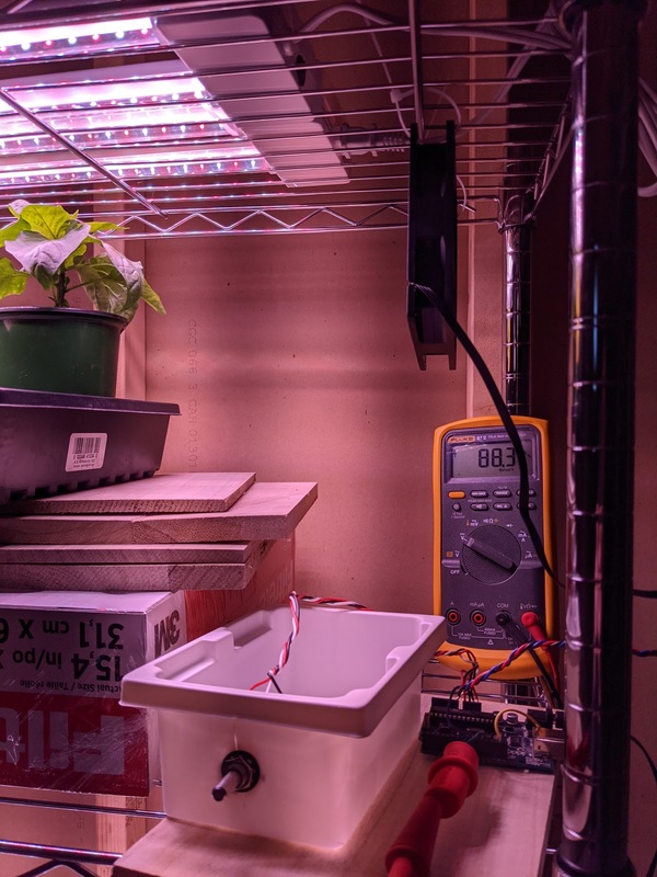
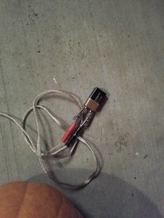
To debug this, I hooked up the TX side of a USB-serial adapter to the RX pin on the Arduino, ran screen(1) on the computer to control it, and started mashing keys. Until I got the irq triggering working properly, I also monitored the output with a DMM just to make sure the output was going low when I held down a key. A test sketch for that looks like this:

SoftwareSerial port2(2, 3);

void setup()
{
  Serial.begin(9600);
  port2.begin(9600);
  Serial.println("Listening...");
}

void loop()
{
  while (port2.available()) {
    Serial.write(port2.read());
  }
}

It works fine. I’ll write about what I was doing with it in some future installment.

Arduino pumpkin lights

Lacking creativity this year, I kind of phoned in the pumpkin carving. We went with regular old triangle-eyed Jack-o-lanterns. It turned out this suited Alex fine: he has decided lately that a certain level of traditionalism is called for. Watching keenly as I cut away bits of pumpkin, he was quick to point out whenever I was doing it the wrong way.

Anyhow, not wanting Halloween to pass buy without doing something new, I decided I’d write a pumpkin light control sketch for Arduino. I have the original board with the Atmega8, and the last time I touched it, the SDK was arduino-0011, which was released about seven years, three domiciles, and one country ago. Since then, I’m happy to see that arduino-mk landed in Debian, and the SDK hasn’t changed APIs in any noticeable way, so it was easy to get back up and running.

The concept is pretty simple: write PWM patterns to an output pin to control the brightness or on/off state of the pumpkin light. I came up with three patterns: fade up and down; random toggle; and sequential stepping. The sketch code is over here.

Arduino light controllerOn the hardware side, I used 3 LEDs for each pumpkin, snipped from a roll that I had left over from my cabinet lighting project. The LEDs expect a +12V supply. On the spool, they are wired in series with a 150 ohm resistor and each LED has a 2.7V voltage drop. Powering that would stretch the Arduino, so I used a separate 12V power supply for those, and used the Arduino to switch an NPN transistor corresponding to each light. I soldered the LEDs to some speaker wire and put the rest of the components on an Arduino protoshield inside a box. This was essentially a lunch hour’s worth of work to get the basic functionality going, and then a little more time to make it neat.

This year Alex and Ian went as Bumblebee and Iron Man respectively (-ENOTPICTURED). Sadly, with store bought costumes — homemade ones will have to wait until one of us learns to sew something other than kites.

DWM-W034 UART

In response to my previous post about UART access on the Alfa AWUS036NHA, I got a nice email from Jim Ewing about the DWM-W034, an ath9k_htc device that apparently is embedded inside HDTVs and readily available for $10. He found the TX/RX pins on the board, and it looks like it would be a bit easier to put a socket on one of these compared to the Alfa since there are no pesky chips nearby.

With his permission, and so that this information doesn’t get lost to the sands of time, here’s the pic he sent me. Enjoy!

Reserialized

I got a shiny new device today and the first thing I did was crack it open and heat it to 680 degrees. A good feeling.

The device in question is an ath9k_htc USB wifi dongle. A colleague suggested this one has an easy to access UART because they brought out the TX/RX pins out from the SoC to dedicated pads. He and I apparently have different definitions for “easy.” Unlike the TP-Link routers which give you through-holes to work with, these are simply SMT pads, and they are tiny in comparison. My soldering iron tip is at least double the size of the pad. Yes, it is somewhat better than trying to solder directly to the pins on the SoC, but not by a whole lot.

As it happens, this is my first attempt at soldering SMT. What could go wrong?

Because the pads are small I used some wire-wrap wire (30 gauge? All I know is that it’s at least two stops smaller than the smallest hole on my wire stripper: getting insulation off was “fun”). During my comedic attempts at getting the wires stuck in the right places, I managed to completely obliterate one of the two pads. Luckily, the one I screwed up was the RX pin, which I don’t really need or care about. Having got the TX and ground wires (badly) soldered in place, I made a some circumspect passes with the magnifying glass and continuity tester to convince myself there were no shorts.

Even so, I am as surprised as you are that it actually worked when I turned it on the first time. And the wifi still works too.

==>[cUSB_REQ_COMP]: 0x%08x
VendorCmd: DownloadComplete!
5. usb only!!
 A_WDT_INIT()
 ==>warm start<==
ALLOCRAM start 0x50d80c size 106484
Enable Tx Stream mode: 0x367
USB mode: 0xf
[+++Magpie_init]
[+++VBUF_init(100)]
[+++VBUF_init(100)]
: Attaching the driver
: Vendor id 0x168c Dev id 0x24
ath_pci_probe 24
 ath_hal = 0x00510928 

        =>[dnQ] 0x0050f288 
[       =>[upQ] 0x0050f264 
[       =>[hp dnQ] 0x0050f240 
[       =>[mp dnQ] 0x0050f21c 
[Tgt running]

Scoped

G#I have this more-expensive-than-my-car hunk of metal on loan for the next few weeks. It’s a pretty far cry from the old Tektronix analog scopes I trained on back in the day (which, at the time, were also much more expensive than my then-primary mode of transportation: shoes). As a warmup exercise, I hooked it up to the output of my guitar amplifier and played an A, which you can see pictured. You can also see that I’m apparently tuned down a half-step as the frequency measured on the scope is about a semitone shy of 220 Hz.

Making wavesThis was a neat teaching opportunity for my four year-old: I showed Alex visually that sound is just made up of different kinds of waves. Later at bathtime he connected that with the physical waves he was making in the tub: “Just like music!” he said.

Pumpkins all Pumpkiny

It is a bit late for a Halloween post, but insert lame excuse here. Consider it a counter-balance to the force that causes Christmas decorations to show up in stores in September.

IMG_4305This year I chose Toopy and Binoo, a Canadian children’s cartoon pair that you have probably never heard of, as subjects for my pumpkin carving. Unfortunately, the pumpkins shriveled quite quickly, and the designs didn’t lend themselves well to preservation, so by Halloween, they grew a toothpick scaffolding to maintain their facade. Next year, I believe I’ll try not cutting all the way through to avoid such issues. (I’m not sure what that technique is called, but some of the more artistic neighbors employed it to great effect.)

5 minute pumpkinImprovised pumpkin lightInside these gourds I used little battery-powered LED lights made for the purpose instead of actual candles. While LED lights don’t look nearly as nice as real candles, one need not care so much about potentially setting things on fire. On the evening of the 31st, as a few groups of kids had already arrived and absconded with their hard-earned treats, I found myself with a third pumpkin untouched by blade, but no light (or candle) to go in it, should I decide to carve it. Then, I remembered my extra spools of SMT LEDs from the cabinet lighting project. I calculated that a 9 volt battery could power three such LEDs for about 10 hours (that estimate was conservative by a factor of 3, it turned out — I need to go back to EE school). Thanks to various other projects, I already had some speaker wire with alligator clips on each end, so, in the course of 5 minutes, I threw together a functional pumpkin light, carved a few holes in the pumpkin, and called it a day. No need to clean out the guts when open flames are not a factor.

IMG_4423For his first Halloween, Ian went as a dragon. Typical of his recent enthusiasm for all things space-related, Alex went as an astronaut. Instead of saying “trick-or-treat,” he would announce, “Hi, I’m Alex. I’m an astronaut!” Much candy was received, all the same.